3.2 What are OSIC tools?
Table of contents
Open-Source Integrated Circuit tools (OSIC) are a collection of free and open-source software applications used for the design, simulation, layout, and verification of integrated circuits. They aim to provide an open, accessible alternative to expensive commercial Electronic Design Automation tools like Cadence and Virtuoso, traditionally used in the semiconductor industry.
Note: In this course, we will follow the pre-compiled Docker image named IIC-OSIC-TOOLS based method which allows for circuit design on a virtual machine on virtually any type of computing equipment.
3.2.1 Xschem
1. Schematic Design in the Design Cycle
In electronic product development, the first step is typically drawing the circuit diagram using an interactive computer program called a schematic editor. Once the schematic is completed, the circuit connectivity and device list (this is collectively called as the netlist) can be generated. This netlist is then used by a circuit simulator such as NGSPICE to perform simulations and verify the circuit functionality before moving to fabrication.
2. Overview of XSCHEM
XSCHEM is a powerful and user-friendly schematic capture tool designed primarily for VLSI (Very Large Scale Integration) circuit design. It allows designers to interactively enter an electronic circuit using a graphical interface and generate netlists for various simulation and design tools.
Key Features of XSCHEM:
- Interactive schematic entry
- Efficient handling of large and hierarchical designs (up to many levels 10+ levels deep).
- Support for multiple netlist formats.
- Optimized rendering and netlisting engines to manage large-scale System-on-Chip (SoC) designs efficiently.
These features made xschem a suitable software in the open-source analog IC design path. Further its interactive yet very simple user interface for schematic designs, symbol allocation, parametric handling, and behavioral mode support-like features made it unique.
Example: Large Hierarchical Design in XSCHEM Below is an image showing a VLSI System-on-Chip (SoC) design imported into XSCHEM. This demonstrates XSCHEM’s capability to handle very large designs with deep hierarchies and complex structures.
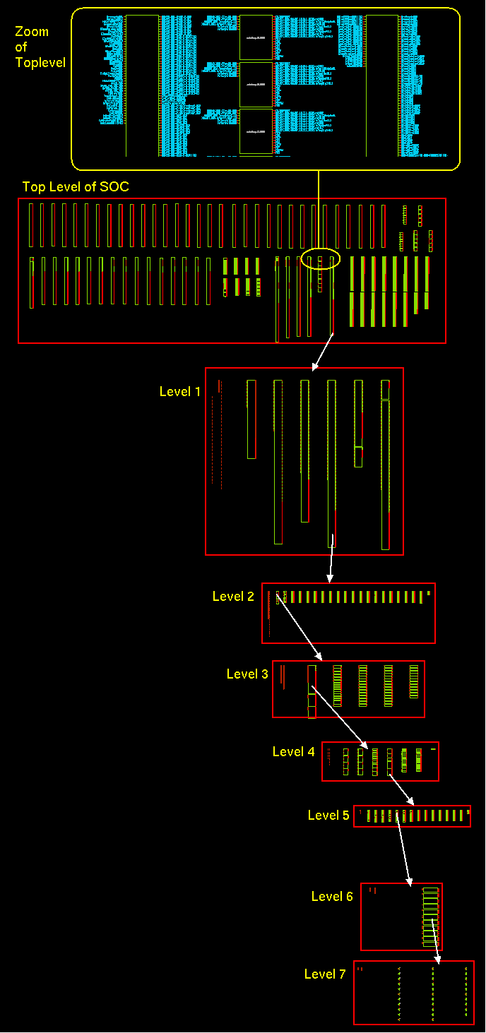
Figure: Complex SOC design in xschem
Note: While initially intended for IC design, XSCHEM has recently expanded to support PCB workflows through the tEDAx format.
3. Install xschem
In this course, instead of installing xschem separately from github repository we will follow the Docker-based method. If you have done the installation correctly, you can open the Xschem software by simply typing xschemin the terminal after you run the docker image.
Figure: Xschem opening window with Skywater 130 and IHP PDKs
4. Design a schematic
Xschem provides different elements like symbols, wires, text, polygons, etc. for schematic designing. ths can be insert by just using Shift + I. The symbols used in the design process will depend on the PDK.
5. Netlist Formats Supported by XSCHEM
XSCHEM currently supports three netlist formats:
| Netlist Format | Purpose |
|---|---|
| SPICE | For analog and mixed-signal circuit simulation. |
| VHDL | For digital simulation and synthesis workflows. |
| VERILOG | For digital simulation and hardware description. |
For future reference:
- How to Set Netlist Mode:
- Use the Options menu and select between modes.
- Alternatively, press Shift + V to cycle through modes.
- How to Generate Netlist:
- Press the Netlist button located at the top-right of the menu bar after the schematic is designed.
- Or simply press the n key.
- The netlist file will be created in the defined simulation directory, ready for use with simulators or downstream tools.
3.2.2 Ngspice
Ngspice is an open-source spice simulator for electric and electronic circuits. It is used for analog, digital, and mixed-signal simulations. Model parameters are provided by ngspice collections, by the semiconductor device manufacturers, or from semiconductor foundries. The user can add circuits as a netlist, and the output is one or more graphs of currents, voltages and other electrical quantities, or it can be saved in a raw data file.
As an open-source software Ngspice supports Verilog-A Device Models, Mixed-Signal Co-Simulation, dealing with User-Defined Models, Programming in Ngspice with an internal scripting language, Circuit Optimization, Statistical Circuit Analysis like Monte Carlo and noise source simulations, RF analysis, and TCAD Integration. These features make ngspice very special and user friendly.
1. Install NGSPICE
Included in the IIC-OSIC-TOOLS Docker image.
2. Running a Basic Simulation
First we have to create a netlist describing this circuit using Xschem. The netlist is the input to ngspice, telling it about the circuit to be simulated. With some simulation commands, this input cares for reading and parsing the netlist, starting the simulation, and plotting the output. Below is the basic simulation for a CMOS inverter.
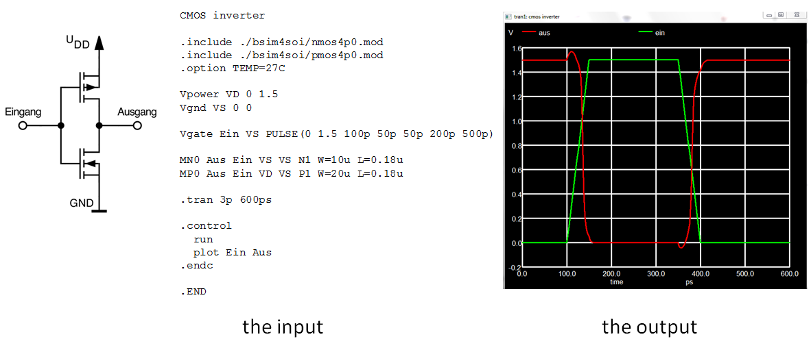
Figure:Simulation for CMOS inverter
3. Types of Analysis
i.DC Analysis (Operating Point and DC Sweep) :Operating Points Calculates steady-state node voltages and branch currents and DC Sweep, Varies a DC source over a range to observe the circuit response.
General form:
.dc srcnam vstart vstop vincr [src2 start2 stop2 incr2]
Examples:
.dc VIN 0.25 5.0 0.25
.dc VDS 0 10 .5 VGS 0 5 1
.dc VCE 0 10 .25 IB 0 10u 1u
.dc RLoad 1k 2k 100
.dc TEMP -15 75 5
ii.AC Small-Signal Analysis :Evaluates the frequency response of the circuit using small AC input signals.
Example: (Basic RC circuit)
r 1 2 1.0
c 2 0 1.0
vin 1 0 dc 0 ac 1 $ <--- the ac source
.options noacct
.ac dec 10 .01 10
.plot ac vdb(2) xlog
.end
iii.Transient Analysis :Simulates time-domain behavior of the circuit when inputs change with time.
General form:
.tran tstep tstop <tstart <tmax>> <uic>
Examples:
.tran 1ns 100ns
.tran 1ns 1000ns 500ns
.tran 10ns 1us
iv.Pole-Zero Analysis :Finds the poles and zeros of a circuit’s transfer function for frequency and stability insights. General form:
.pz node1 node2 node3 node4 cur pol
.pz node1 node2 node3 node4 cur zer
.pz node1 node2 node3 node4 cur pz
v.Small-Signal Distortion Analysis :Measures how much harmonic distortion is introduced by the circuit for small inputs. General form:
.noise v(output <,ref>) src ( dec | lin | oct ) pts fstart fstop
+ <pts_per_summary>
Examples:
.noise v(5) VIN dec 10 1kHz 100MEG
.noise v(5,3) V1 oct 8 1.0 1.0e6 1
3.2.3 netgen
Netgen is a tool used for Layout vs. Schematic (LVS) verification, which is a crucial step in ensuring that the final layout matches the intended circuit design. Here Netgen compare the genertaed netlists from the schematic and a netlist extracted from the layout. The layout tool such as magic and Klayout supports extracting the netlist for LVS. Netgen will compare these two files to decide if the two netlists are identical. If it is not identical, we have to identify the differences and change the layout and/or the netlist so that they are identical. The identical layout and schematic also ensures somewhat that the circuit will work as expected.
We need to do this check because when transforming from schematic to layout, you might make different mistakes, for example, a short circuit. The connection and the terminal in the layout are different from the schematic. LVS is an important step in analog design flow to ensure that your layout is identical to your schematic.
1. Key Features
- Hierarchical netlist comparison
- Integration with Magic and KLayout
- Error reporting for mismatches such as:
- Missing devices
- Incorrect connectivity
- Parameter mismatches
2. Running Netgen LVS
Running LVS with netgen is very simple, you just need to run netgen with three arguments. First open netgen using The first one and the second one are the two netlists that we created. The third argument is a configuration file that is already available from the PDK. You might have a look at $PDK_ROOT/$PDK/libs.tech/netgen/setup.tcl
To run an LVS check:
netgen -batch lvs layout.spice schematic.spice ihp-sg13g2_setup.tcl
3. Normal Workflow
- Schematic design in Xschem and get the netist.
- Layout in Magic.
- Extract layout netlist using Magic or Klayout.
- Run Netgen to compare schematic and layout netlists.(both netlists sholud be in same directry where netlist is called)
LVS passed is a good sign that your schematic and your layout are equivalent. However, it might not tell you about the important characteristics in analog design. You should run the post layout spice simulation with the parasitic extraction to verify that the parasitic after layout do not affect your design very much.
3.2.4 OpenEMS
OpenEMS is an open-source electromagnetic field solver specifically designed for high-frequency RF and microwave circuit simulations. It uses the Finite-Difference Time-Domain (FDTD) method, which provides full-wave 3D EM analysis and supports both transient and frequency domain results.
Applications in IC Design and RF Systems:
- On-chip antennas
- Transmission line simulations
- Electromagnetic interference (EMI) analysis
- Substrate coupling and shielding analysis
- RFIC packaging analysis
OpenEMS is particularly useful for simulating structures with spatial non-uniformity or complex geometries that cannot be simplified into circuit models.
1. Install OpenEMS
Included in the IIC-OSIC-TOOLS Docker image.
2. Key Features of OpenEMS
-fully 3D Cartesian and cylindrical coordinates graded mesh. -Multi-threading, SIMD (SSE) and MPI support for high speed FDTD. -Octave/Matlab and Pyhon-Interface -Dispersive material (Drude/Lorentz/Debye type) -Field dumps in time and frequency domain as vtk or hdf5 file format -Flexible post-processing routines in Octave/Matlab and Python
3. Workflow to Simulate with OpenEMS
You can use open EMS in python enabled CMI. make sure that open EMS and python is installed there. for more information about OpenEMS simulations please visit here
3.2.5 QUCS-S
1. Overview
Qucs-S (Quite Universal Circuit Simulator - SPICE edition) is a circuit simulation interface that unifies powerful simulation engines like Ngspice, Xyce, and QucsatorRF under a simple GUI built using the Qt6 toolkit. Unlike standalone simulators, Qucs-S is not a simulation engine but a graphical front-end for these backends.
Its main purpose is to merge the power of SPICE simulators with the intuitive, schematic-based graphical interface of the original Qucs project. Simply, this gives a more commercialized user-friendly version for open sources simulations.
For more details please visit here
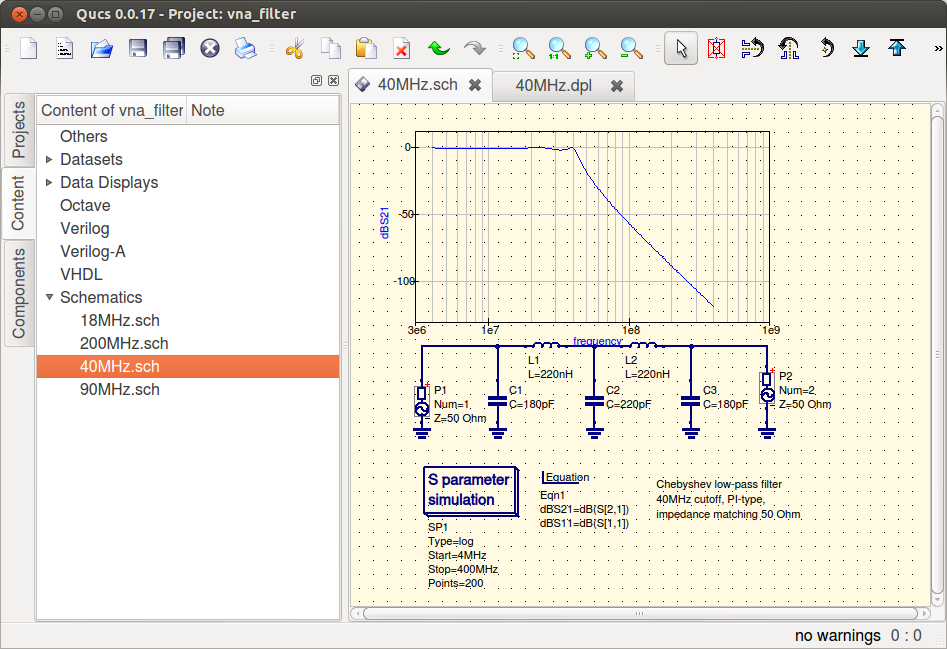
Figure: Simualtion using QUSC
2. Supported Simulation Backends
- Ngspice
- Recommended backend.
- Supports mixed-level/mixed-signal simulation.
- Xyce
- SPICE-compatible.
- Offers advanced RF simulations, including harmonic balance analysis.
- QucsatorRF
- Used primarily for RF and microwave circuits.
- Supports microstrip lines and waveguides.
3. Key Features
- Unified GUI for multiple simulation backends.
- Quick switching between simulation engines without restarting.
- Direct support for SPICE models from datasheets.
- Tuner mode for real-time parameter adjustment.
- Support for .PARAM statements and Nutmeg postprocessor.
- Nutmeg/XYCE script simulation support (advanced scripting mode).
- Supports digital and RF libraries for backend-specific simulation.
This is ideal for RF and analog front-end circuit designs. This helps to simulate and validate SPICE netlists generated from tools like Xschem. Ngspice backend ensures compatibility with IHP PDK designs.
3.2.6 KLayout
KLayout is a powerful, high-performance open-source layout viewer and editor, widely adopted in both integrated circuit and photonic design workflows. It supports multiple industry-standard file formats such as GDSII, OASIS, DXF, and LEF/DEF, making it highly versatile for layout tasks across various stages of the design flow. KLayout is particularly known for its ability to efficiently handle large layouts, providing seamless zooming, panning, and editing functionalities even with complex designs. One of its standout features is its strong scripting support using both Python and Ruby, which allows users to automate repetitive tasks, extend core functionality, and integrate custom tools directly within the KLayout environment.
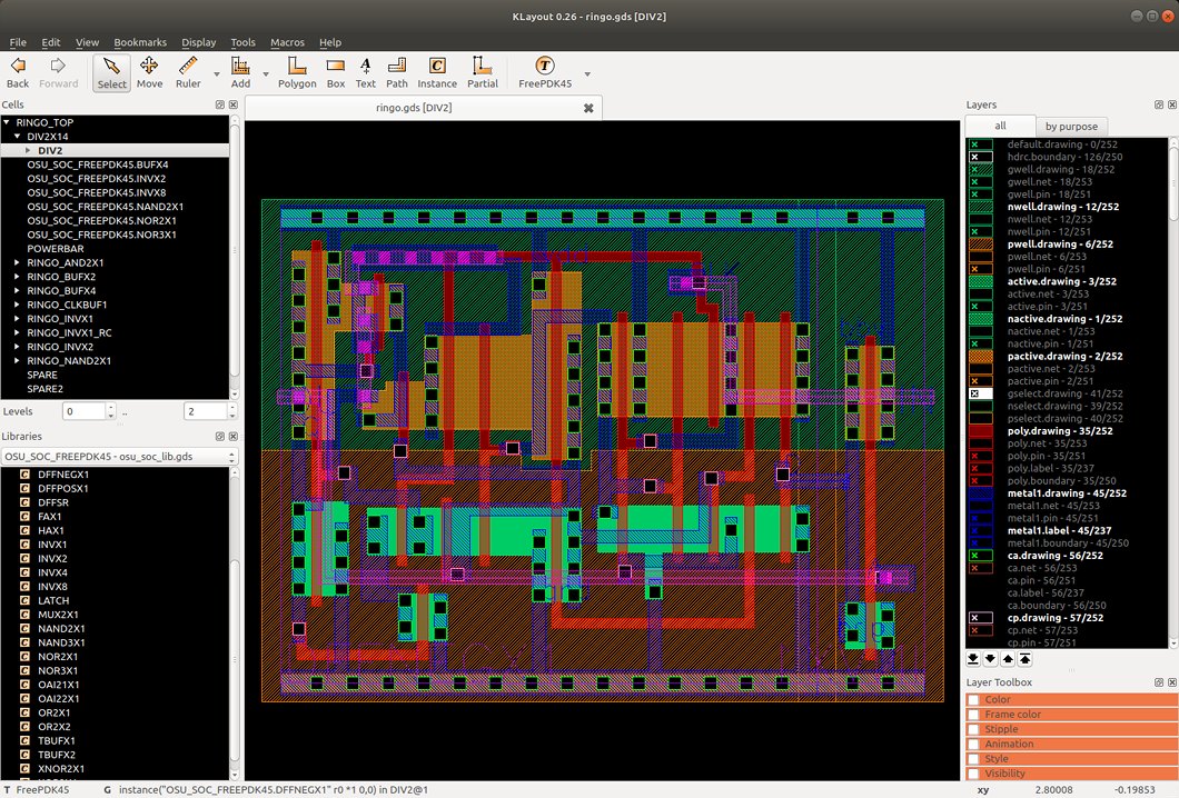
Figure: Xschem opening window with Skywater 130 and IHP PDKs
In terms of design verification, KLayout offers robust built-in capabilities for Design Rule Checking (DRC) and Layout Versus Schematic (LVS), enabling users to validate that their layouts conform to manufacturing rules and accurately represent the corresponding schematics. The tool also supports Parameterized Cells (PCells), allowing designers to create reusable components with customizable parameters, which streamlines layout generation and promotes consistency across designs. Its layer management system is intuitive and feature-rich, offering advanced visibility toggles, color schemes, and grouping mechanisms, which aid in clear and efficient layout navigation. Additional utilities such as net tracing, measurement tools, and geometry processing help users analyze connectivity and layout properties in-depth.
The user interface of KLayout is organized into essential areas that support effective interaction with designs. These include the Hierarchy Browser, which allows navigation through the design’s cell hierarchy; the Layout Canvas, which provides the central workspace for visualization and editing; the Layer Panel, which handles layer-specific settings; and the Navigator, a minimap for quick transitions across large layouts.
Within the OSIC design flow, KLayout plays a crucial role during the post-layout stages. It is commonly used to visualize and review layout files generated by tools such as Magic or itself, ensuring that designs are ready for further verification and fabrication. DRC and LVS scripts can be executed within KLayout to validate compliance with process design kits (PDKs), and minor layout edits or fixes can be made directly within the interface. For more details Official Website.
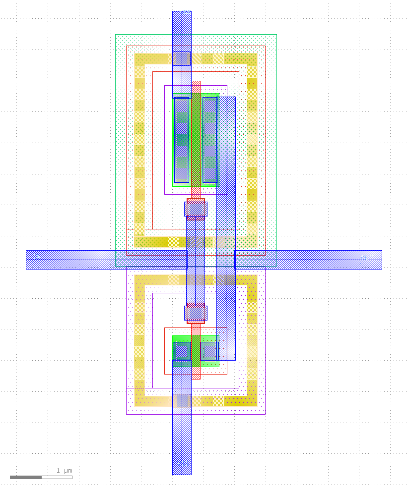
Figure: CMOS inverter using Klayout
IIC osic tools dokcer file includes Klayout also so when we done with the docker configuration parts all these softwares will be in our system for use.