5. Inverter design using OSIC tools
An inverter is a basic and essential logic gate in digital electronics. It takes one input and gives the opposite output—if the input is high (1), the output is low (0), and if the input is low (0), the output is high. Inverters are widely used and serve as the building blocks for more complex digital circuits, making them a great starting point for students learning about integrated circuit (IC) design.
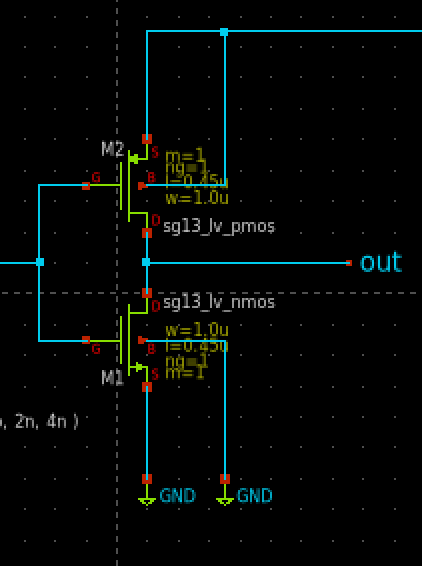
In CMOS technology, an inverter is made using two types of transistors: NMOS and PMOS. These two transistors work together—when one turns on, the other turns off—to create the inverted output. This design is efficient in terms of power and provides strong performance, which is why it is widely used in modern digital systems.
The IHP Open Source PDK allows students and researchers to design and test inverters using the SG13G2 130nm BiCMOS technology. This technology includes both CMOS transistors and high-speed SiGe bipolar transistors, making it suitable for a wide range of applications, including digital, analog, and RF circuits.
By using free and open source tools like Xschem, ngspice, and KLayout, students can go through the full design process—from creating the circuit and running simulations to drawing the physical layout and checking design rules. This hands-on experience is very similar to what engineers do in the semiconductor industry.